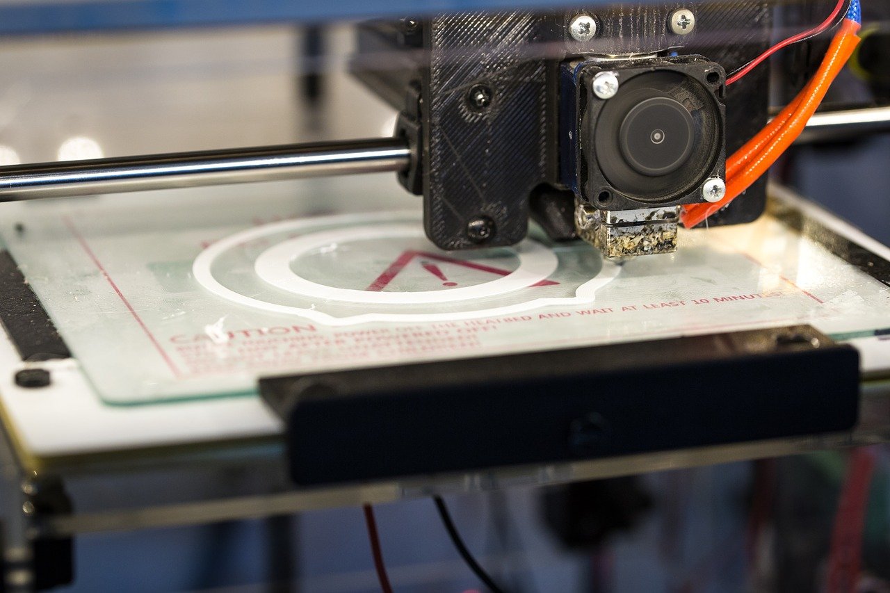

Who likes to play casino games in the Swiss Casino Online already has one or the other game at home and now wants to get more accessories, does not have to buy this. There are many 3D models available on the Internet for free download for the 3D printer. This makes it possible to create individual casino accessories and useful utensils needed for gambling in no time at all. Below are several helpful accessories that you can print at home using a 3D printer.
1. Print game chips
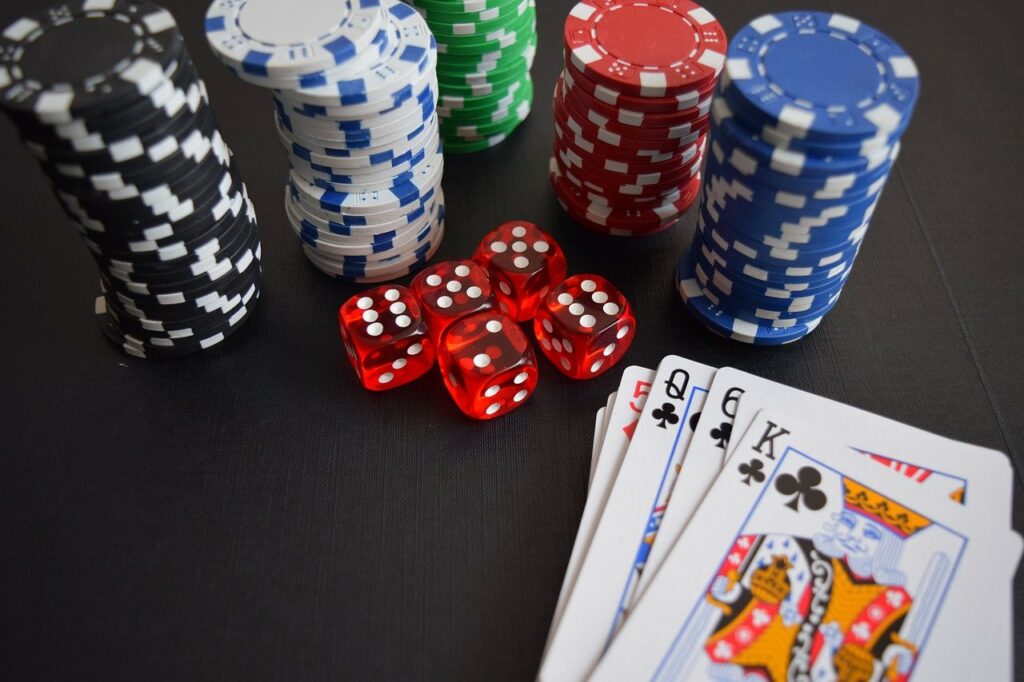
Gambling chips can always be used when gambling at home. Whether for poker or roulette, the round chips can be produced easily with a 3D printer. Matching models can be found on the Internet. It does not have to be the same chips as in the casino. There are no limits to creativity. The design can be individualized. Anyone can use the 3D printer to design their own chips in different colors and sizes. If you want, you can even kill two birds with one stone and print chips the same size as shopping chips or play money. This way, the chips can be used several times. The chips also cut a fine figure as a gift.
2. Print playing cards
Of course, 3D printers can also be used to print playing cards. Whether poker cards, blackjack cards or your own creation, the card games can be printed according to your own wishes. There are different templates for this. These can be decorated with text, photos and other graphics. Thus, an individual card design is created. By the way, the playing cards also make a splendid gift. Be it as an invitation, a thank you or just for entertainment, your own card print is guaranteed to surprise.
3. Print card holder
The card holder is one of the most important utensils in a casino and should not be missing at home. On the one hand you have your hands free for other things, on the other hand the cards can be sorted properly. With a custom card holder from the 3D printer, you can print models that not only allow you to insert cards, but also to move and remove them. You can also print a card holder that can be placed on the table.
4. Print chip holder
Of course, the 3D printer can do even more. Even chip holders for poker chips, roulette chips or other chips can be produced with this printer. If you want, you can immediately print a model that is equipped with a handle and a rotating stand. From the classic design with three compartments to the modern chip holder construction – everything is possible with the 3D printer.
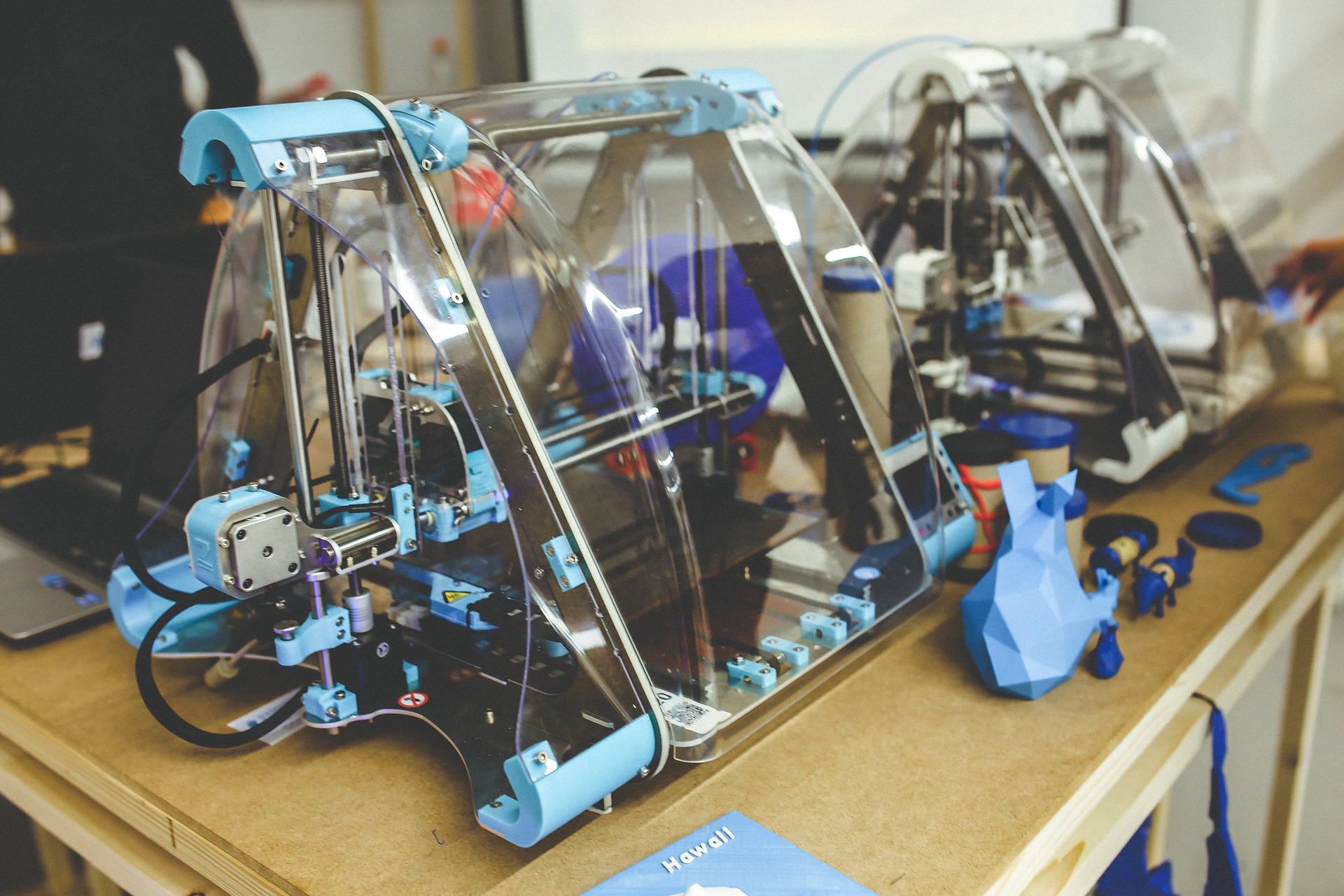
5. Casino accessories soon in 4D
Of course, the 3D printer can print many more items. From a roulette tablecloth to a playing field to card boxes or roulette rakes, many useful items needed in gambling are printable. In any case, 3-D printing continues its triumphal procession unstoppably. The devices have long since developed from high-end products to everyday use. The modern printers are also no longer too expensive. By the way, in the future there will soon be a 4D printing device. This will print objects that can be deformed and can be even better adapted to their purpose.